Packaging of microelectronics circuit is the science and art of establishing interconnections for MEMS and IC devices.
MEMS is relatively a new field which is tied closely with IC micro-fabrication process. All packaging applications can be summed up in
three terms: performance, reliability and cost.
Packaging lab is located in the third floor of the CeNSE building #TF 32, is a 2000 sq feet air conditioning lab, housing Equipments/tools to
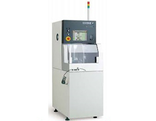
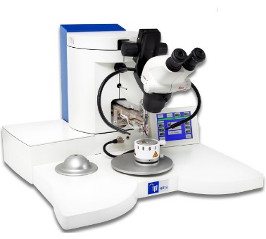
enable packaging of various MEMS and IC devices. The lab has facilities for Wafer Dicing, Die Attach, Ball/Wedge bonding, Laser welding, Soldering,
and High Magnification Microscope for assembly, packaging and testing of MEMS and IC devices. It also has facilities for Low/High pressure calibration,
Acoustic calibration with data acquisition systems for performance studies and characterization of various transducers. As one of the supporting facilities
at CeNSE, MEMS and IC Packaging lab provides all the facilities required to build a packaged device using a wafer.
EQUIPMENTS

PEOPLE
FACULTY
Prof. K.N Bhat
Visiting Professor
knbhat@iisc.ac.in

Prof. M.M Nayak
Visiting Professor
mmnayak@iisc.ac.in
STAFF

Sankaran
Project Associate
samkarankoyili@gmail.com

Jayabal V
Project Associate
jayabal.av@gmail.com
Veera Pandi N
Sr. Faculty Technologist
veerapandin89@gmail.com

M.S Manjunath
Sr. Faculty Technologist
manjunathm@iisc.ac.in

Pavithra B
Project Assistant
pavithrab@iisc.ac.in

Nithin
Project Assistant
nithinbhandary1@gmail.com
RESEARCH
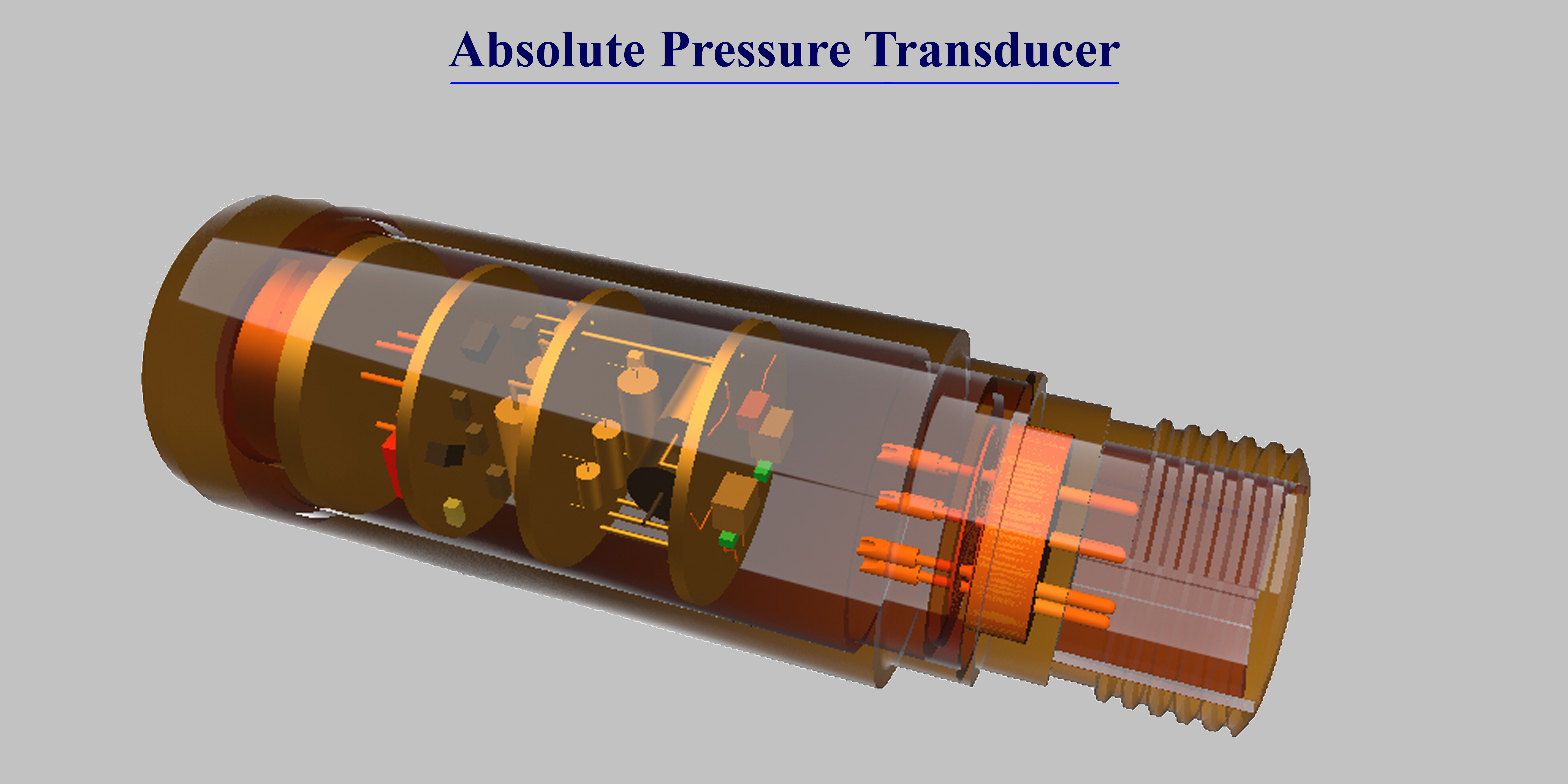
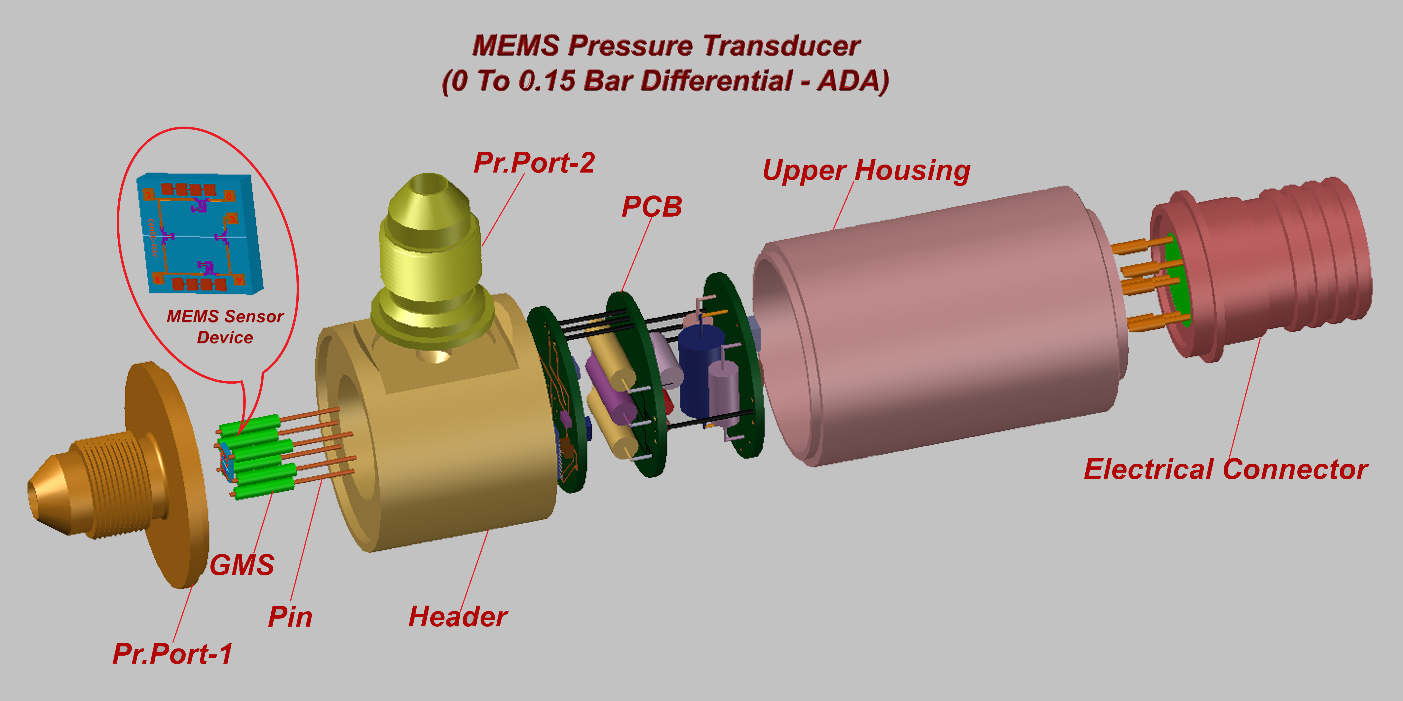
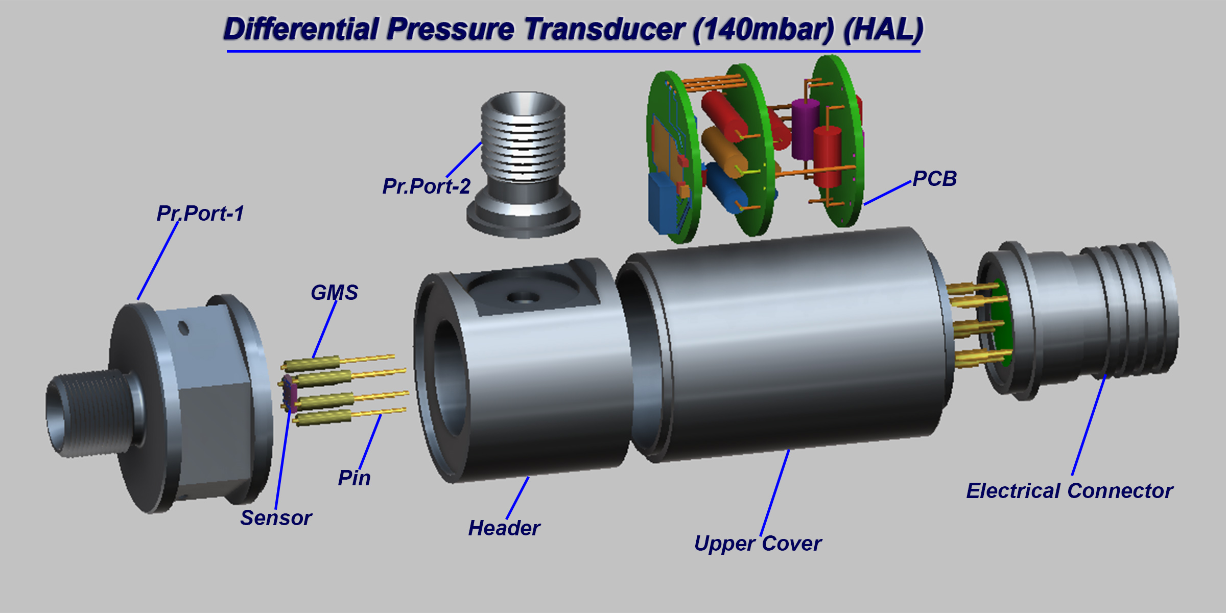
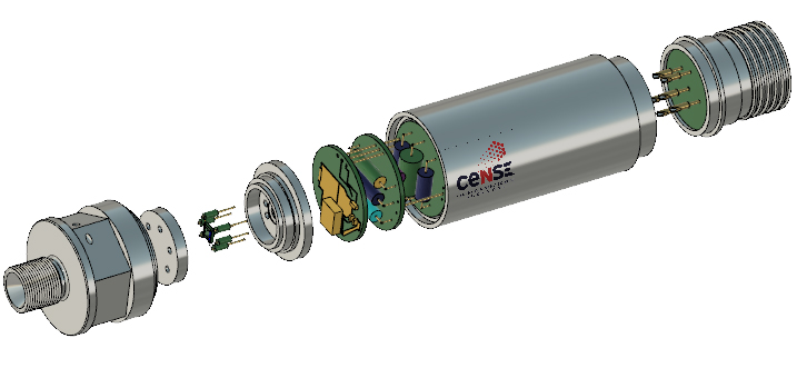
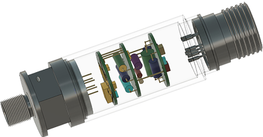
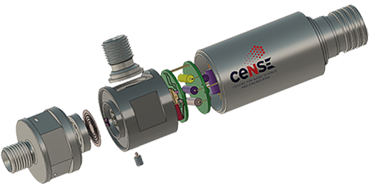
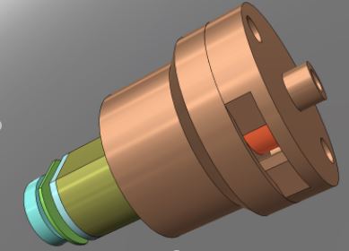
MEMS PRESSURE TRANSDUCER
ABSOLUTE PRESSURE TRANSDUCER
OTHER PROJECTS
LIFE CYCLING SYSTEM
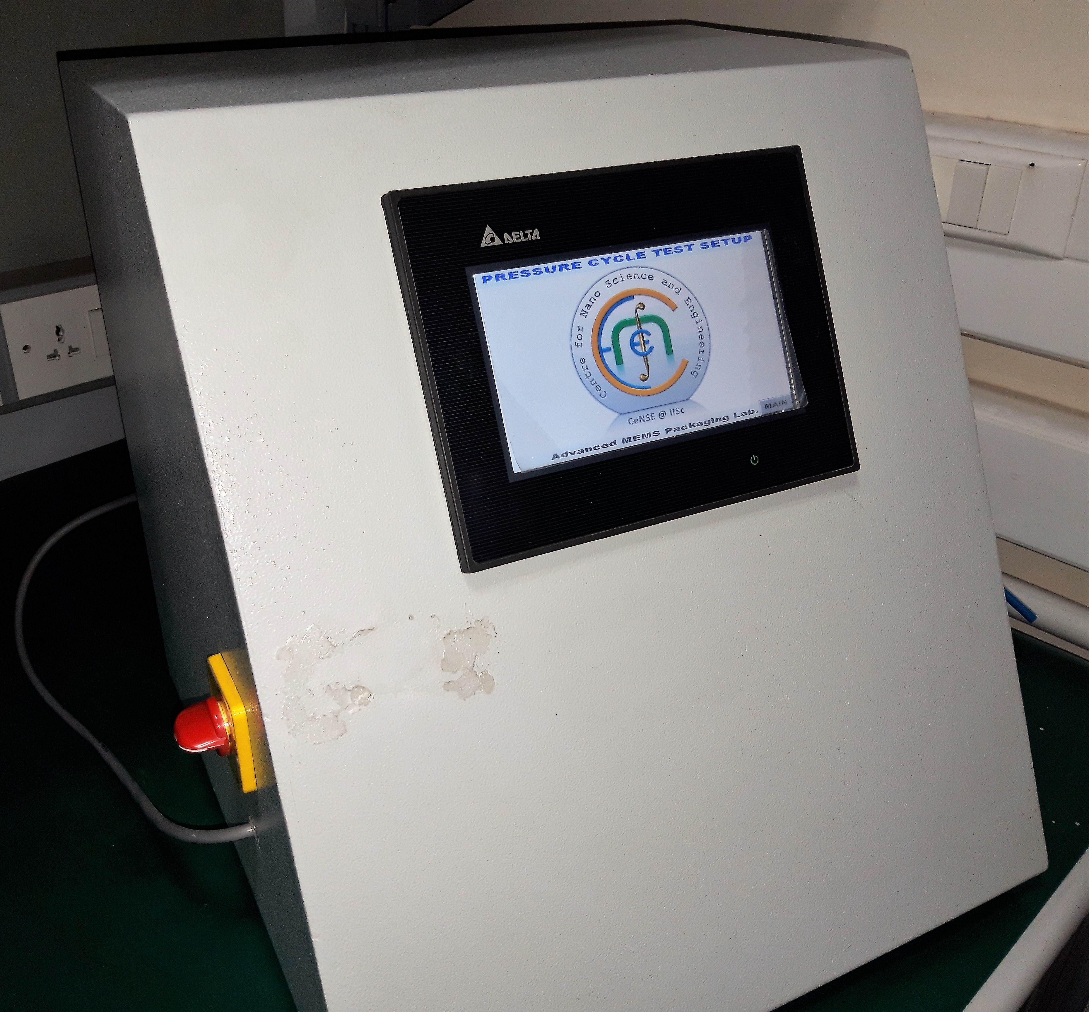
LIFE CYCLING SYSTEM
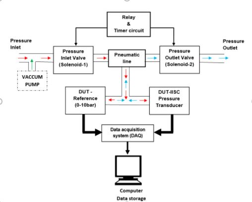
The system mainly developed for study the reliability and ageing effect of the pressure transducers which will going to use on aerospace applications. The Pressure cycle test set up comprises of two solenoid valves – one for pressurizing and the other for depressurizing, an electronic square wave oscillator with transistor relay drive circuit for controlling the “ON” and “OFF” timings of the solenoid valves, power supply for exciting the electronics and solenoid valve, and pneumatic interconnecting adaptors. During the test, for recording the output data of the pressure transducer, data acquisition system is also incorporated in the set up.
OP/1
PARESTATIC PUMP FOR DRUG DELIVERY SYSTEM
POWER DEVICE GaN PACKAGE
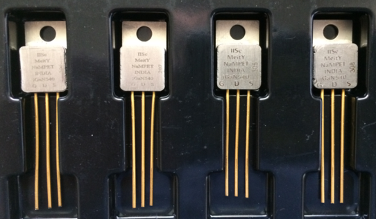
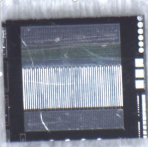
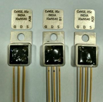
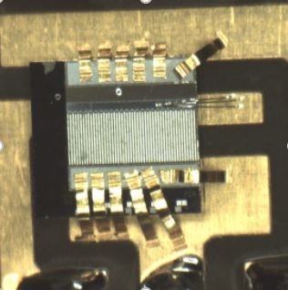
POWER DEVICE GaN PACKAGE
POWER semiconductor device packaging is in many ways similar to that of IC packaging. It provides mechanical support to the fragile chip, electrical interconnections, heat dissipation paths, and protection from the environment. However, there are important differences between the two that are dictated by the functions of the power device. For example, the number of interconnections necessary is substantially less than that of a microprocessor. In a power MOSFET or insulated gate bipolar transistor (IGBT), a minimum of three interconnections are necessary (drain, source, and gate). Power devices usually handle much larger currents and voltages such that they require larger interconnections and more efficient thermal management. Such seemingly minor and simple differences may not be that easy to implement in real package structures because of constraints on the physical properties of the device and package component materials and the thermomechanical issues such as coefficient of thermal expansion (CTE) mismatches that can adversely affect the performance and reliability of the package or module.
OP/3

IOT MODULE
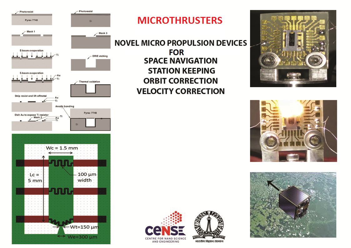
MICROTHRUSTERS
BODY CONDUCTION
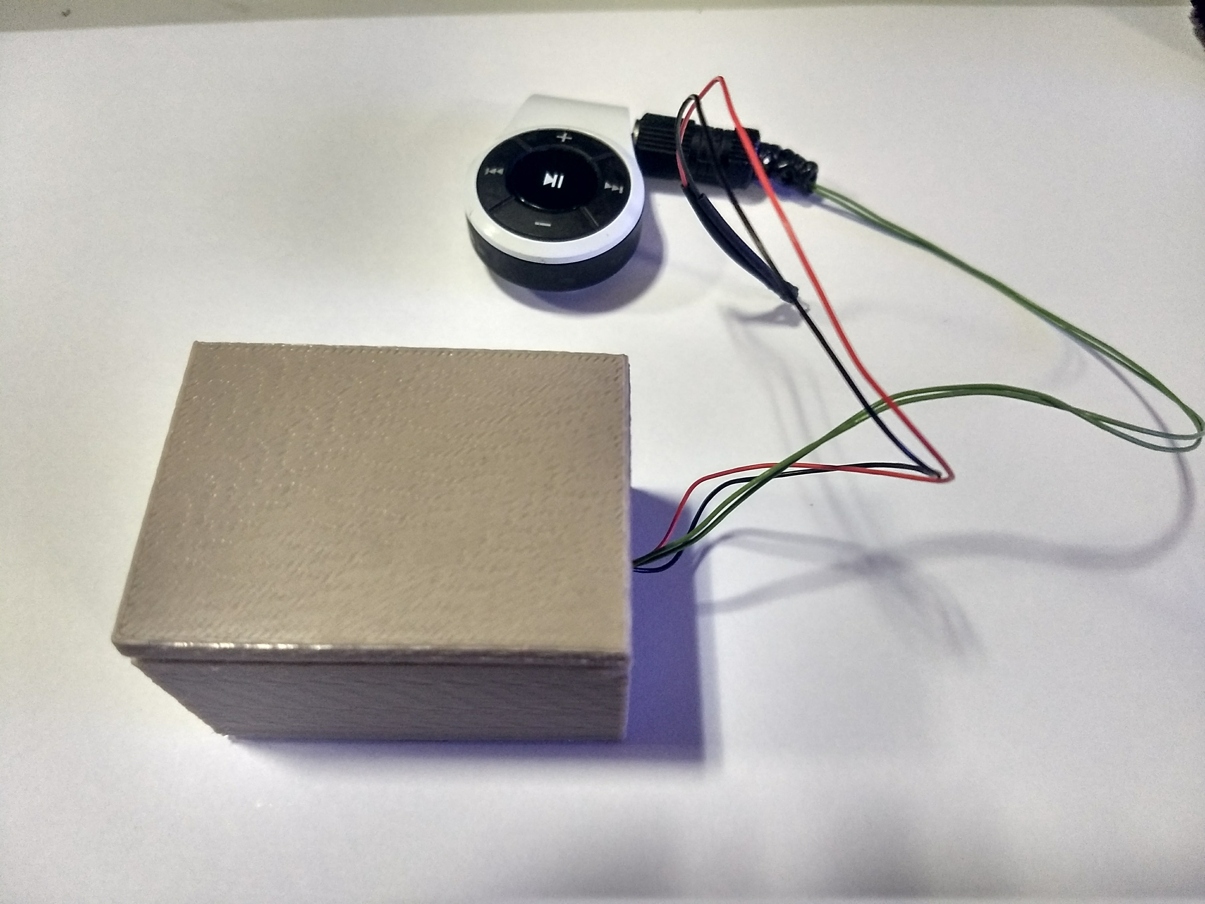
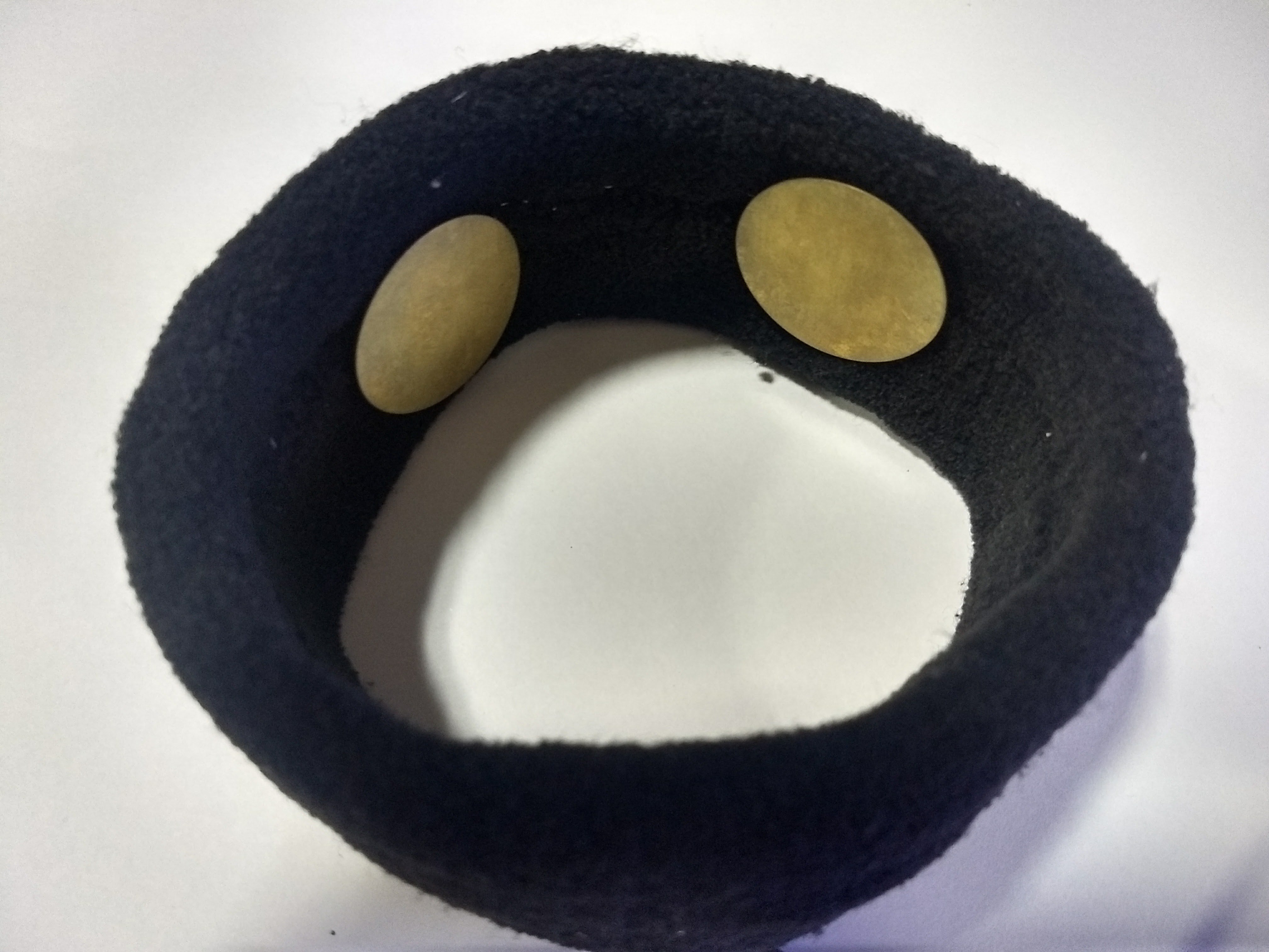
BODY CONDUCTION
We have designed and developed a new hearing aid, named “Body Conduction Hearing Aid”, which is External Wearable Head Band. Conventionally, Sound is a vibration that travels through air as mechanical wave of pressure, reaches ear drums and vibrates. Whereas, In the Body Conduction does not make use of air pressure wave for hearing; Instead piezoelectric actuator is used for generating mechanical wave these wave travel through the human body; resulting in the name ‘Body Conduction’. Hence, ‘Body Conduction Hearing Aid’ is a hearing-aid, for Conductive hearing loss & Sensorineural hearing loss.
The Bone-conduction hearing aid is actuated by PZT Element. We have developed the Prototype and the working model of the same.
Sound energy beats on the body skin by the Body Conduction Vibrator, at the point of beating.Now, the rhythm is taken up by the skin and spreads along the surface of the skin, around the beating point, like micro dimensional ripples, along a disturbed fluid surface. Our Body is primarily a Body of Fluid. The Body Fluid is held in position by skin.
Thus, in the form of mechanical energy, the rhythmic wave moves along skin-surface of the fluid-filled Body. Similar to the way it behaves in the inner-ear cochlea, sound energy swims through the Body fluid and skin; sweeping across teeny, tiny roots of Body hairs that bend and snap. Body is the replica of inner-ear cochlea; with numerous hair anchored on to skin membrane.
Energy fires neurons, bundled into the nerves of touch, the skin nerves or touch nerves. The nerve’s long wires or axons, zings energy forward to lower brain structures, until the energy is analyzed in the speech processing center of the brain.

OP/6
RESOURCES
STANDARD OPERATING PROCEDURE
| Revision | Date | Initiator | Reviewer Signature | Approver’s Signature |
| 1 | 12 Dec 2017 | Manjunath | Jayabal | MM Nayak |
- Purpose
- Scope
- Points to be noted before starting the tool
- Check if all the facilities like Coolant water, Argon gas is turned on.
- Never run the laser with the laser protection door opened, by overriding the interlock.
- CNC part program of the component to be ready before starting the machine.
- Clean the mating parts of the components using Acetone and IPA
- Operating Instructions
- Sample Loading and welding
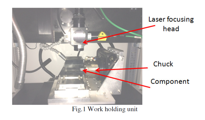
- Load the sample on to the chuck
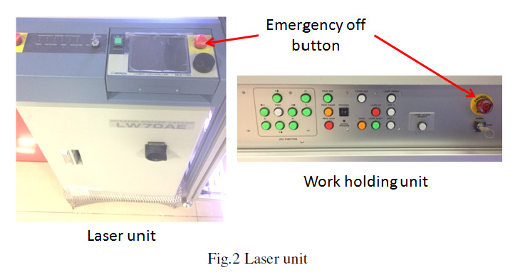
- Turn-on the laser source, work holding machine and log-in in into the system
- Dry run the part program by disabling the laser to confirm the part program is defect free.
- Activate the laser source and weld the component.
- Any malfunction the emergency switches should be pressed immediately.
- Sample Unloading
- Once the welding process is finished the sample can be removed from the chuck
- Precautions
- Never run the laser with the laser protection door opened, by overriding the interlock.
- Dry run the part program by disabling the laser to confirm the part program is defect free.
- Activate the laser source and weld the component.
- Any malfunction the emergency switches should be pressed immediately.
- Contact Point
This document describes the steps to be followed by the user, to weld components.
It covers the instructions for basic operations of the system, the safety precautions to be
followed while operating the system and the penalty, in case of any deviations from
following SOP.
If you feel any difficulty while operating or any issue with the tool. Please contact the tool
owners
Manjunath: 9731387979
Jaybal: 9886058035
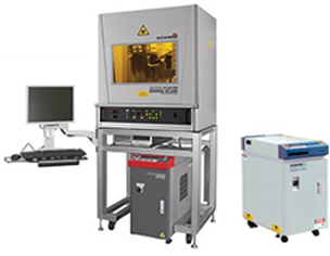
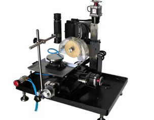
Laser Tool pictures:
If any other than above stated, Please contact the tool owner.
NOTE:
Any deviations from this SOP will be considered as a breach of User Agreement
conditions and will result in cancellation of access to the tool.
| Revision | Date | Initiator | Reviewer | Approver’s Signature |
| 1 | 21 Dec 2017 | Manjunath | Pavitra /Manjunath | MM Nayak |
- Purpose
- Scope
- Points to be noted before starting the tool
- Make sure beforehand the device is leak proof and can withstand high pressures at-least 1.5 times the actual operating pressure.
- Mount the device with appropriate fittings and 'O' rings, only hand tight the device.
- Release the relief valve and prime the tool by pressurizing and depressurizing and verify that there are no air bubbles.
- Operating Instructions
- Sample Loading and welding
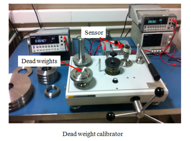
- Mount the sensor always upright and do a leak test at low pressures and close the relief valve.
- Gradually increase/decrease the pressure/depressurizing by adding /removing the weights in suitable increments and calibrate the sensor.
- Sample Unloading
- Make sure to unload the component only after depressurizing and opening of the relief valve.
- Precautions
- In-case of any emergency depressurize and open the relief valve
- Contact Point
This document describes the steps to be followed by the user, to calibrate pressure sensor device.
It covers the instructions for basic operations of the system, the safety precautions to be followed while operating the system and the consequences, in case of any deviations from following SOP.
If you feel any difficulty while operating or any issue with the tool. Please contact the tool
owners
Pavitra: 9449947188
Manjunath: 9731387979
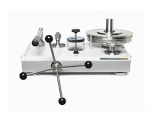
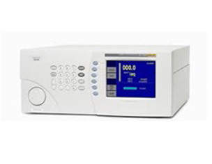
Equipment pictures:
If any other than above stated, Please contact the tool owner.
NOTE:
Any deviations from this SOP will be considered as a breach of User Agreement
conditions and will result in cancellation of access to the tool.
| Revision | Date | Initiator | Reviewer | Approver’s Signature |
| 1 | 12 Dec 2017 | Manjunath | Shankaran /Manjunath | MM Nayak |
- Purpose
- Scope
- Points to be noted before starting the tool
- Cordon off the area around the tool.
- Mount the device with appropriate fittings and point the device away from operator.
- Make sure beforehand the device is leak proof and can withstand high pressures at-least 1.5 times the actual operating pressure.
- Operating Instructions
- Sample Loading and welding
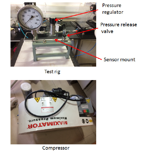
- Mount the sensor which has to be calibrated and do a leak test at lower pressures (10-20) bar and slowly increase the pressure by closing the input check valve and check for any pressure drop.
- Increase the pressure gradually up to 300 bar and close the release valve and turn off the compressor.
- Ascending pressure test - Test the sensor by gradually increasing adjusting the pressure regulator to the required steps of pressure
- Descending pressure test - by gradually releasing the pressure using the pressure release valve in the required steps.
- Sample Unloading
- Once the calibration is completed depressurize by opening the relief valve completely and unload the sample.
- Precautions
- In-case of any emergency turnoff the Maximator Compressor and release the pressure immediately by turning the pressure release valve.
- Contact Point
This document describes the steps to be followed by the user, to calibrate pressure sensor.
It covers the instructions for basic operations of the system, the safety precautions to be
followed while operating the system and the consequences, in case of any deviations from
following SOP.
If you feel any difficulty while operating or any issue with the tool. Please contact the tool
owners
Sankaran: 9632839996
Manjunath: 9731387979
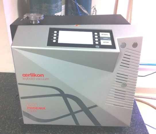
Equipment pictures:
If any other than above stated, Please contact the tool owner.
NOTE:
Any deviations from this SOP will be considered as a breach of User Agreement
conditions and will result in cancellation of access to the tool